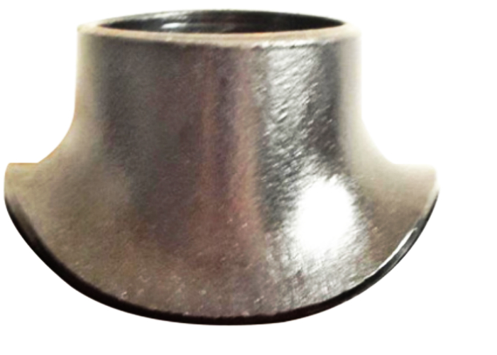
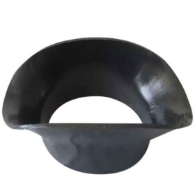
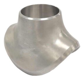
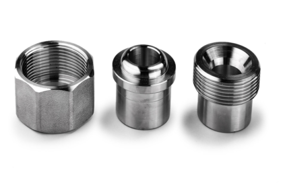
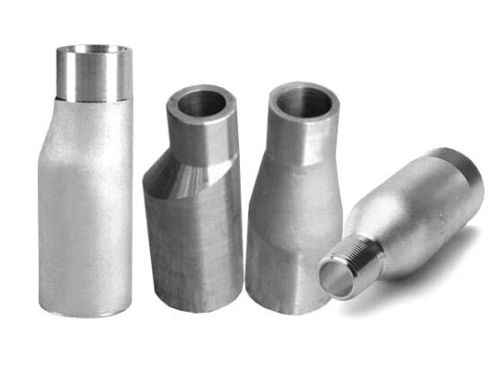
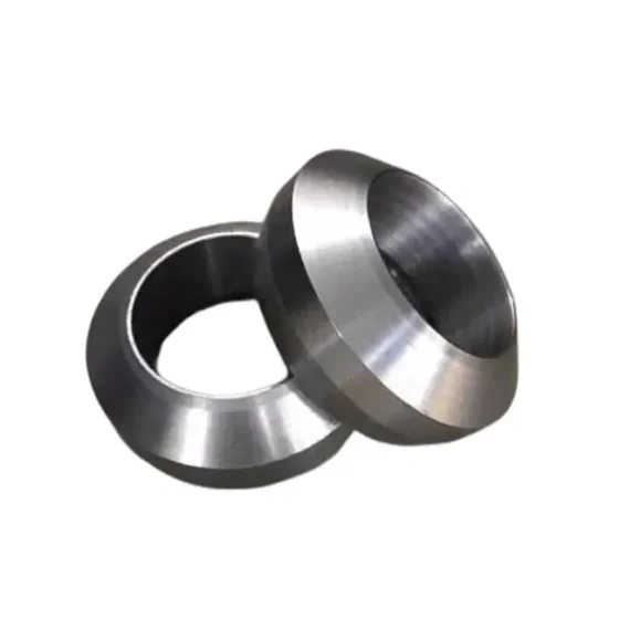
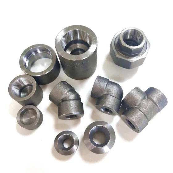
What is Sweepolet?
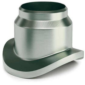
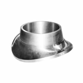
Sweepolet, on the other hand, is a socket-welded branch fitting. It is designed with a gradual radius that allows smooth flow and minimizes turbulence. Sweepolet is preferred in applications that require a larger flow rate and where the pipe wall thickness is heavy. Socket welding provides a strong and leak-proof connection that can withstand high-pressure applications.
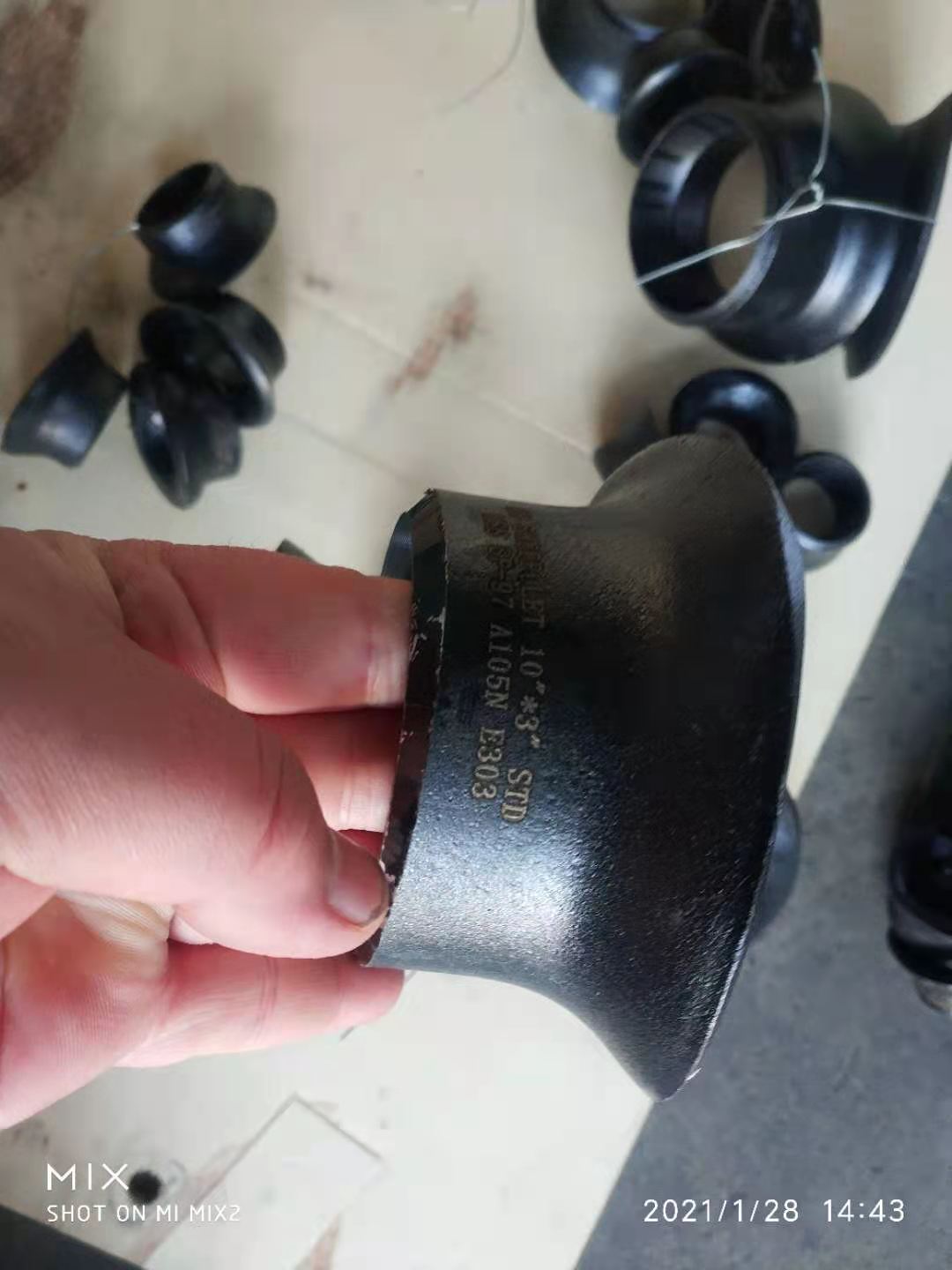
Sweepolets are primarily developed for high-yield pipe used in oil and gas transmission lines. Sweepolets provides good flow pattern, and optimum stress distribution.
Sweepolet is a contoured, integrally reinforced, butt-weld branch connection with a low stress intensification factor for low stresses and long fatigue life. The attachment weld is easily examined by radiography, ultrasound and other standard non-destructive techniques. They are manufactured to meet specific reinforcement requirements.
Differences Between Weldolet and Sweepolet
One of the main differences between Weldolet and Sweepolet is the type of connection used. Weldolets are butt-welded fittings, and Sweepolets are socket-welded fittings. Also, the design of the two fittings is different. Weldolet has a small outlet, while Sweepolet has a gradual radius. Another difference is in the applications they are used for. Weldolets are suitable for low-pressure applications with thin pipe walls, while Sweepolets are suitable for high-pressure applications with heavy pipe walls.
Which one should you choose?
The choice between Weldolet and Sweepolet depends on the requirements of your application. If you need a smooth flow and require a reliable connection for low-pressure applications with thin pipe walls, then Weldolet is the best choice. On the other hand, if you need a larger flow rate and require a strong and leak-proof connection for high-pressure applications with heavy pipe walls, then Sweepolet is the right choice.
|
Product name
|
Sweepolet
|
|
Standard
|
ASME/ANSI B16.5/16.36/16.47A/16.47B, MSS S44, ISO70051, JISB2220, BS1560-3.1, API7S-15, API7S-43, API605, EN1092
|
|
Materials
|
Nickel Alloy: ASTM/ASME S/B366 UNS N08020, N04400, N06600, N06625, N08800, N08810, N08825, N10276,N10665,N10675
Super Stainless Steel: ASTM/ASME S/A182 F44, F904L, F317L Stainles steel: ASTM/ASME S/A182 F304, F304L, F304H, F316, F316L, F321, F321H, F347H Duplex Steel: ASTM A182 F51, F53, F55 Alloy Steel: ASTM/ASME S/ A182 F11, F12, F22, F5, F9, F91 Carbon Steel: ASTM/ASME S/A105, ASTM/ASME S/A350 LF2, ASTM/ASME S/A694/A694M, F42, F52, F56, F60, F65, F70….ASTM/ASME S/A350LF2, ASTM/ASME S/A694/A694M, F42, F52, F56, F60, F65, F70…. |
|
Dimension
|
Header pipe size:1/2″-24″
Branch pipe DN15-DN1800
|
|
Marking
|
Supply Logo + Standard + Size(миллиметр) + HEAT NO +or as your requirement
|
|
Test
|
Chemical Component Analysis, Mechanical Properties, Metallurgical Analysis, Impact Testing, Hardness testing , Ferrite Testing,
Intergranular corrosion testing, X-ray Inspection (RT), PMI, PT, UT, HIC & SSC test, etc. or as your requirment |
|
Brand
|
PSCO
|
|
Сертификаты
|
API, ISO, SGS, BV, CE, PED, KOC, CCRC, PDO, CH2M HILL and etc.
|
|
Advantages
|
1. Abundant stock and prompt delivery.
2. Reasonable for whole packages and processes. 3. 15 years’ QC team service & sales management API& ASTM trained engineers. 4. More than 150 customers spread worldwide. (Petrofac, G.S Engineer, Fluor, Hyundai Heavy industry, Kuwait National Oil, Petrobras, PDVSA, PetroEcuador, SHELL, etc.) |
Sweepolet Pipe Intersection
Defects at weld locations of a sweepolet pipe intersection
This example shows analysis of defects at the header and branch weld locations of a sweepolet pipe intersection. The header pipe has a 36 inch outer diameter and the branch an 8 inch outer diameter. This pipework is used in gas transmission pipelines.
The analyses required the modelling of full circumferential defects of various depths at two weld locations – one in the header and one in the branch. Defects were to be considered on the inner and outer walls. Due to the load cases that were analysed it was necessary to generate a full model in addition to quarter and half symmetry models. The combination of load cases, crack sizes and crack positions gave a total requirement of more than 100 separate analyses.
The finite element model consisted of 20 noded brick elements in the pipe intersection region with 8 noded shells away from the intersection.
The analyses generated stress intensity factor distributions along the crack fronts. These were used as input to a reliability analysis
https://www.pipeflangefittings.com/client-showcase-02/

 Глобальное превосходное универсальное решение для трубопроводов
